Understand image sensor output format – Raw RGB
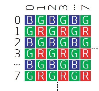
Each pixel on the image sensor has the color coating on top, therefore it can only collect one color of the light per pixel, namely, R, G, B. We call this RGB sensor. If this color information has not been processed and output data is called raw RGB. Normally, the color pattern on the sensor is BGBGBG for the first row and GRGRGR for the second row. However, due to different arrangement of color coating , pixel output format can be in 4 types: GR/BG, RG/GB, BG/GR and GB/RG. Therefore, we need to know the exact color format before feeding this data to ISP for processing. Otherwise, the image reproduced will be in wrong color.
RGB data output can be in 8 bits, 10 bits and etc, the more bits mean higher accuracy of color information will be provided. That’s why we can see the terms of 8bit RGB, 10bit RGB or RAW8, RAW10 in the sensor data sheet.
For some RGB sensor, besides raw RGB, it can output different format of RGB data. There are some commonly used formats as described below.
- RGB565: every pixel has 16bits, 5 bit for R, 6 bits for G and 5 bits for B, arrangement like this: RRRRRGGGGGGBBBBB
- RGB555: every pixel still has 16 bits but the highest bit is ignored, every color has 5 bits in this case: xRRRRRGGGGGBBBBB
- RGB24: every pixel has 24 bits, include RGB data each of 8bits: BBBBBBBBGGGGGGGGRRRRRRRR
Normally, for higher resolution sensor, it outputs raw RGB data for faster frame rate. Back end ISP will handle all the color interpolation and image processing. Other RGB or YUV format only used in less pixel count sensor and with built in ISP. Here are some examples for OV sensor
OV7725: VGA, output format – 8bit YUV/YCbCr4:2:2, RGB565/555/444, GRB4:2:2 and raw RGB 8bit/10bit
OV7740: VGA, output format – 8/10bit raw RGB, 8bit YUV
OV9734: 1280×720, output format -10bit raw RGB
OH02B10: 2MP, output format -10bit raw RGB